Comparative analysis of brushless dc and switched reluctance motors for optimizing off-grid water pumping
- Select a language for the TTS:
- UK English Female
- UK English Male
- US English Female
- US English Male
- Australian Female
- Australian Male
- Language selected: (auto detect) - EN
Play all audios:

ABSTRACT Off-grid water pumping systems (OGWPS) have become an increasingly popular area of research in the search for sustainable energy solutions. This paper presents a finite element
method (FEM)-based design and analysis of Brushless-DC (BLDC) and Switched Reluctance Motors (SRM) designed for low-power water pumping applications. Utilizing adaptive finite element
analysis (FEA), both motors were designed with identical ratings and design parameters to ensure a fair comparison. The design geometries adhere to the NEMA 42 standard. An (_n_ + 1) switch
converter topology was implemented to energize SRM phases, while a Cuk converter coupled with a three-phase voltage source inverter (VSI) was used to power the BLDC motor. The study provides
a comprehensive comparative analysis of the torque profiles of both motor types under identical operating conditions. The BLDC motor achieved a maximum torque of 11.5 Nm and an efficiency
of 91.9%, while the SRM demonstrated a maximum torque of 3.8 Nm and an efficiency of 94.6%. The torque ripple of the BLDC motor was significantly lower (0.73 pu) compared to the SRM (1.19
pu), indicating smoother operation. Simulation results obtained using advanced computational electromagnetic tools highlight the performance efficiencies and potential advantages of each
motor type for off-grid water pumping systems. This research investigates the viability of both BLDC and SRM technologies in enhancing the efficiency and reliability of OGWPS, with the BLDC
motor showing superior performance in terms of torque and operational smoothness. The simulation results of converter topologies used for respective motors have been further validated using
experimentation on respective prototype motors. SIMILAR CONTENT BEING VIEWED BY OTHERS ANALYSIS AND CONTROL OF GRID-INTERACTIVE PV-FED BLDC WATER PUMPING SYSTEM WITH OPTIMIZED MPPT FOR DC-DC
CONVERTER Article Open access 29 October 2024 HIGH GAIN CHOPPER SUPPLIED FROM PV SYSTEM TO FED SYNCHRONOUS RELUCTANCE MOTOR DRIVE FOR PUMPING WATER APPLICATION Article Open access 15
September 2022 POWER CONTROL OF AN AUTONOMOUS WIND ENERGY CONVERSION SYSTEM BASED ON A PERMANENT MAGNET SYNCHRONOUS GENERATOR WITH INTEGRATED PUMPING STORAGE Article Open access 30 November
2024 INTRODUCTION Off-grid electrification remains a significant challenge in many developing countries, where reliable access to electricity is still a luxury rather than a norm. This lack
of electricity severely hampers water pumping operations in these regions, directly impacting the livelihoods of a large portion of the global population1,2. The absence of a reliable water
supply affects agriculture, health, and overall quality of life, leaving communities struggling to meet their basic needs. In this advanced technological era, it is disheartening that such
fundamental needs are still unmet for millions of people3. To address these critical issues, this research paper proposes a solution for off-grid water pumping applications by designing and
optimizing special electric motors—specifically Brushless-DC (BLDC) motors and Switched Reluctance Motors (SRM)—that can be powered by batteries or solar energy. The solutions presented here
focus on getting reliable, efficient, and a sustainable way to pump water in off grid areas. Conventional electric motors, such as induction motors are widely used for water pumping
applications. However, these motors operate on single-phase or three-phase AC supply, which is not inherently compatible with the DC supply typically available from batteries or solar panel.
While the conventional motors can be energized using this available DC supply, the conversion of this available DC supply to single-phase or three-phase AC supply leads to significant
inefficiencies4,5. In addition, the conversion equipment raises the overall cost and size of the system, which makes it less practical for off grid applications where resources and space are
typically limited. This study introduces the use of BLDC and SRM motors as viable alternatives to overcome these inherent inefficiencies and limitations associated with conventional
electric motors. These motors are designed to operate efficiently with DC supply, eliminating the need for complex and costly conversion equipment. The proposed system utilizes the benefits
of BLDC and SRM technologies to offer a more efficient and cost effective, and reliable solution for off grid water pumping6. This approach not only addresses the immediate need for water
pumping but also contributes to the broader goals of sustainable development and improved quality of life in off-grid communities. The availability of modern PM with significant energy
density led to the development of DC machines with PM field excitation in the 1950s7. The introduction of PMs to replace electromagnetic poles with windings that require an electrical power
source has led to compact DC machines8. Likewise, in synchronous machines, the conventional electromagnetic field poles in the rotor are replaced by the PM poles, thereby saving the slip
rings and the brush assembly9. With the advent of switching power transistors and silicon-controlled rectifiers in the late 1950s, the mechanical commutator was replaced by an electronic
commutator in the form of an inverter. These two developments contributed to the development of PMSMs and Brushless DC machines10. The DC machine’s armature needs not to be on the rotor if
the mechanical commutator is replaced with its electronic version. This allows the machine’s armature to rest on the stator, allowing for better cooling and higher voltages, since there is
significant free space in the stator for insulation. The excitation field that used to be present at the stator is transferred to the rotor with the PM poles11. These special electric
machines are nothing more than an inverted DC machine with the field and armature reversed from stator to rotor and rotor to stator respectively and are called Brushless-DC (BLDC) motors. On
the other hand, switched reluctance motor is a type of synchronous motor that operates on the principle of magnetic reluctance12. Unlike traditional motors that use permanent magnets or
electromagnets on the rotor, the SRM has a simple rotor with salient poles with no magnets13. The stator contains windings that create a magnetic field when energized. DC phase commutated
supply in phase sequence is provided for energizing the stator phase windings14. It requires an additional electronic switching circuit to convert the constant DC supply to phase commutated
sequential supply. With the advent of high-frequency power switching devices available nowadays, SRM has become an interesting topic of research for various applications15. Different
varieties of motors have been designed in recent years for water pumping applications but somehow, they lack their applicability in off-grid areas. Some of the recent articles published in
reputed journals have been reviewed and cited above in Table 1. Some of the recently published work related to FEM-based design and analysis of SRM and BLDC motors have been cited in this
section. The authors of the research paper24 presented a meticulous examination of a novel BLDC motor design. Leveraging the FEM, the study not only explores the motor’s design intricacies
but also conducts torque analysis. The double-slot surface and spoke-type configuration highlight innovation in motor design, promising potential advancements in efficiency and performance.
Authors in the paper25 introduced a novel controller, combining linear-quadratic regulator and proportional-integral-derivative methods through a mixture of experts (MoE) for a single-phase
PM brushless DC external rotor motor. The dynamic model, incorporating cogging torque and electromotive force, is analyzed using FEM-based tools Ansys-Maxwell and MATLAB. Results show
enhanced performance and robustness during load disturbance. The research presented in26 addresses energy-efficient groundwater harvesting challenges in agriculture, focusing on India. With
bore wells often reaching 450–500 m depth, traditional induction motor pumps face inefficiencies due to a shift in the operating point and increased impeller stages. The study proposes a 15
kW submersible tubular brushless permanent magnet motor (STBLPM) as a superior alternative. Finite Element Method (FEM) analysis optimizes and predicts efficiency, with real-time
implementation showing an 8% efficiency improvement over conventional submersible tubular induction motors. The paper27 introduces a four-phase SRM drive designed for ceiling fans. Utilizing
an asymmetric bridge converter for independent phase control and simplicity, the drive eliminates the need for speed and current feedback loops, avoiding current sensors and complex
computational logic. Analytical, simulation, and experimental studies demonstrate the drive’s effectiveness, showcasing low current ripple and acoustic noise essential for ceiling fan
applications. The research presented in the paper28 focuses on designing a 2 kW Switched Reluctance Motor for an electric autorickshaw, considering the demand for higher speeds. Various
stator-rotor teeth combinations are evaluated, and a suitable combination is selected. To address windage loss at elevated speeds, the study explores the impact of rotor slot profiles on
drag force, a key factor influencing windage loss. While significant advancements have been made in the field of electric motors and renewable energy systems, the application of these
technologies to off-grid water pumping systems (OGWPS) remains underexplored. Conventional solutions typically involve the use of induction motors powered by AC supply, which necessitates
the conversion of available DC power from solar panels or batteries. This conversion process introduces inefficiencies and increases both the cost and complexity of the system. Although
Brushless-DC (BLDC) and Switched Reluctance Motors (SRM) have been studied extensively in other applications, their specific performance characteristics and potential benefits for off-grid
water pumping systems have not been thoroughly analyzed and compared. The existing literature lacks a comprehensive comparative study that evaluates these motors under identical conditions,
focusing on their suitability for low-power off-grid applications. Moreover, there is a need to optimize motor designs to enhance efficiency and reliability in such application area.
Additionally, practical aspects such as the design of appropriate converter topologies for these motors and the detailed analysis of their torque profiles, efficiency, and operational
characteristics are often overlooked in existing research. This gap highlights the necessity for an in-depth investigation into the implementation and performance of BLDC and SRM motors
specifically designed for off-grid water pumping applications. This paper presents the design framework and optimization of both a Brushless-DC (BLDC) motor and a Switched Reluctance Motor
(SRM) designed for water pumping applications in off-grid systems. The study implements adaptive FEA to conduct performance analysis of both motors, ensuring fast convergence of results and
maintaining identical design parameters for a fair comparison. The simulation models feature simplified construction, reducing complexity in both the converter design and control strategies,
making them more practical for off-grid applications. Both motors are demonstrated to be highly efficient and suitable for off-grid water pumping systems (OGWPS), addressing the
inefficiencies and limitations of conventional motors used in similar applications. This study provides an in-depth comparative analysis of the performance characteristics of BLDC and SRM
motors, including torque profiles, efficiency, and operational characteristics, under identical operating conditions. The paper introduces novel converter topologies designed for the
efficient operation of BLDC and SRM motors in off-grid environments, significantly reducing conversion losses and improving overall system efficiency. By examining detailed torque profiles,
efficiency metrics, and operational characteristics, this research enhances the understanding of how BLDC and SRM motors perform in practical off-grid water pumping scenarios, providing
valuable insights for engineers and practitioners. This research investigates the potential of BLDC and SRM technologies to provide sustainable and cost-effective solutions for off-grid
water pumping, contributing to broader goals of rural electrification, sustainable development, and improved quality of life in developing regions. The simulation results have been validated
experimentally on the prototype of SRM and BLDC motors of similar ratings. The study suggests that both these motors can perform better than conventional induction motors for off-grid water
pumping applications. The reason behind choosing these two dissimilar technologies for comparison is that both of these motors; SRM and BLDC come from the family of Special Purpose
Machines. These machines are different in construction as well as working from the conventional machines (typically Induction motors) used for water pumping applications. Additionally, these
motors are highly efficient and their efficiencies and torque profile are comparable when designed for similar ratings. The methodology of the proposed work has been briefly discussed in
Sect. 2. The system design equations and equivalent circuit models have been discussed in Sect. 3. Section 4 of this paper deals with the briefing of converter topologies used for the
excitation of respective motors. FE-based framework and modeling, Adaptive FEA, and analysis of air gap parameters of SRM and BLDC motor have been detailed in Sect. 5 while Sect. 6 presents
a comparative analysis of torque profiles of the designed SRM and BLDC motor models. The conclusion drawn from the existing study has been written in Sect. 7 of this research paper. PROPOSED
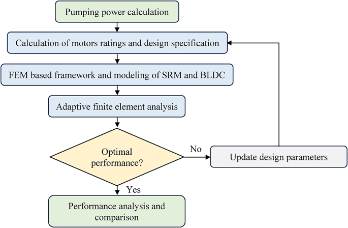
METHODOLOGY The research work presented in this paper deals with designing the low-power rated switched reluctance motor and brushless-DC motor for off-grid water pumping applications. The
design procedure of motors for the present work has been elaborated using a flow chart, shown in Fig. 1. Before designing any electric motor, it is very crucial to estimate the ratings of
the motor. The design procedure of motors starts by calculating pumping power based on the physical parameters discussed in Sect. 2.1. Further, the power ratings of motors have been
estimated based on calculated pumping power and shaft power. The dimensional specifications of the motors have been calculated using NEMA 42 standards, discussed in Sect. 2.2. Framework and
modeling of SRM and BLDC motors have been done using the finite element method discussed in Sect. 2.3. PUMPING POWER CALCULATION The calculation of pumping power or hydraulic power depends
upon physical constraints like the density of the fluid, fluid flow rate, acceleration due to gravity, and water head. Equation (1) shows the mathematical equation to calculate the hydraulic
power (in kW)29. $$\:{\text{P}}_{\text{h}}=\:\frac{\text{q}{\uprho\:}\text{g}\text{h}}{3.6\text{X}{10}^{6}}$$ (1) Where, \(\:{\text{P}}_{\text{h}}\) is the hydraulic power (in kW),
\(\:\text{q}\) represents the flow rate of fluid (in \(\:{\text{m}}^{3}/\text{h}\)), \(\:{\uprho\:}\) denotes the density of the fluid (in \(\:\text{k}\text{g}/{\text{m}}^{3}\)),
\(\:\text{g}\) is the acceleration due to gravity (typically 9.81 \(\:\text{m}/{\text{s}}^{2}\)), and \(\:\text{h}\) represents the water head (in meters). The amount of mechanical power
required at the shaft of the motor is called the shaft power and can be calculated by taking the ratio of hydraulic power to the efficiency of the mechanical pump as represented in Eq. (2).
$$\:{\text{P}}_{\text{s}\text{h}}=\:\frac{\text{H}\text{y}\text{d}\text{r}\text{a}\text{u}\text{l}\text{i}\text{c}\:\text{P}\text{o}\text{w}\text{e}\text{r}}{\text{E}\text{f}\text{f}\text{i}\text{c}\text{i}\text{e}\text{n}\text{c}\text{y}\:\text{o}\text{f}\:\text{m}\text{e}\text{c}\text{h}\text{a}\text{n}\text{i}\text{c}\text{a}\text{l}\:\text{p}\text{u}\text{m}\text{p}}=\:\frac{{\text{P}}_{\text{h}}}{{{\upeta\:}}_{\text{p}\text{u}\text{m}\text{p}}}$$
(2) Equations (1,2) have been used for the calculation of pumping power, following the SCH 40 standards of pipes30. A pipe of 2-inch diameter has been selected to pump the water from a
specific water head of 10 m. The maximum flow rate of water through a 2-inch diameter (SCH 40) pipe is equal to 45 gal/m (= 10.2206 \(\:{\text{m}}^{3}/\text{h}\))31. The density of water is
998 \(\:\text{k}\text{g}/{\text{m}}^{3}\)32. The efficiency of medium to small range of centrifugal mechanical pumps ranges between 50 and 70%33. Typically, the value of efficiency equal to
60% has been selected for calculating the shaft power. The calculated values of hydraulic power and shaft power are 0.28 kW and 0.46 kW respectively and have been represented in Table 2.
MOTORS RATINGS AND DESIGN SPECIFICATION Switched Reluctance Motor and Brushless-DC Motor which belong to the family of special electric motors have been designed and simulated using FEM
based computational tool, Ansys Maxwell. The design procedure starts by estimating the ratings of the motors. Both the motors have been designed for the same power and voltage ratings, as
shown in Table 3. The significance of keeping the same power and voltage rating is to get the response of the designed models to be concluded at identical parameters and conditions. Figure 2
shows the block diagram representation of powers at different stages of the water pumping system whereas Fig. 3 shows the input DC supply voltage waveform. The ratings of the electrical
motors for the water pumping load are estimated based on the amount of hydraulic power required at the suction side of the pump. Hydraulic power for the present work is calculated using Eq.
(1), discussed in Sect. 2.1. The input power fed to the mechanical pump is the shaft power which is provided by the electric motor. The calculated value of shaft power required for the
present work is 460 W, discussed in Table 2. Therefore, considering the losses and efficiency of motors, the ratings of both SRM and BLDC are estimated to be 500 W, discussed in Table 3.
NEMA 42 standards have been used for the dimensional framework of both the machines. Table 4 shows the dimensional specifications of both the SRM and BLDC motors, which have been calculated
considering NEMA 42 standards for 500 W motors. FINITE ELEMENT METHOD The Finite Element Method (FEM) is a powerful numerical technique used in engineering and physics to solve complex
partial differential equations by dividing a continuous domain into smaller, finite-sized elements. This method has applications in various fields, including electrical motor design. FEM
involves several stages in the analysis of a problem: pre-processing, processing, and post-processing, discussed using a block diagram in Fig. 4. These stages are sequential and essential
for obtaining meaningful results from FEM simulations34. The pre-processing stage is initiated by geometrical modeling of SRM and BLDC motor referring to dimensional parameters as shown in
Table 4. Based on the design geometry and framework, the discretization of elements (also called mesh generation) is done. Further, the selection of material types and boundary conditions
are also involved in the pre-processing stage. In the next stage of FEM i.e., the processing stage, an appropriate solver is used to solve the system of equations generated during
pre-processing. For solving the assembly of system equations of the designed SRM and BLDC Motor, the conjugate gradient iterative method35 is discussed using Eqs. (3, 4).
$$\:{\text{P}}_{\text{k}}=\:{\text{r}}_{\text{k}}-\:\sum\:_{\text{i}<\text{k}}\frac{{\text{P}}_{\text{i}}^{\text{T}}\text{A}{\text{r}}_{\text{k}}}{{\text{P}}_{\text{i}}^{\text{T}}\text{A}{\text{P}}_{\text{i}}}{\text{P}}_{\text{i}}$$
(3) Where, \(\:{\text{x}}_{\text{k}}\) represents the value that gets updated after each iteration, \(\:{\text{r}}_{\text{k}}\) is the negative gradient of the function at
\(\:{\text{x}}_{\text{k}}\) and \(\:{\text{P}}_{\text{k}}\) is the conjugate gradient of the function. The next optimal location is given by involving the following iterations.
$$\:{\text{x}}_{\text{k}+1}=\:{\text{x}}_{\text{k}}+\:{\text{a}}_{\text{k}}{\text{P}}_{\text{k}}$$ (4) The Conjugate Gradient (CG) method is a highly efficient iterative solver widely used
in FEM for electromagnetic problems, especially when the system matrix is large, sparse, symmetric, and positive-definite. In electromagnetic FEM, the discretization of Maxwell’s equations
results in a system of linear equations. Instead of solving directly, CG exploits the matrix’s sparsity by generating a sequence of conjugate directions, ensuring efficient search in the
solution space. With each iteration, the method calculates a residual vector to assess how far the current solution deviates from the exact one and updates ‘_X__’_ accordingly. This process
continues until the residual falls below a predefined tolerance, indicating convergence. The CG method is suitable tool for electromagnetic problems because it averts matrix inversion,
making it computationally efficient for large-scale systems often encountered in wave propagation, eddy currents, and magnetostatic simulations. Further, adaptive Finite Element Analysis
(FEA) has also been used for the refinement of the simulation results. Adaptive FEA is a powerful method for solving electromagnetic problems by dynamically refining the mesh to enhance
accuracy in regions with high field gradients or error concentration. In this method, the domain is initially discretized with roughly a mesh, and the solution to Maxwell’s equations is
computed using FEM. The posteriori error estimator is generally used for the estimation of error in the solution. It identifies areas where the discretization error exceeds a predefined
threshold. These areas normally occur near sharp material boundaries, edges, corners, or regions with rapidly varying electromagnetic fields. The mesh is refined adaptively in these specific
regions by subdividing elements, increasing the polynomial degree of basic functions, or both. The FEM solution is then recomputed on the refined mesh, and the process iterates until the
global error meets the specified tolerance. Adaptive FEA ensures computational efficiency by concentrating resources where needed, avoiding unnecessary refinement in low-error regions. This
method is beneficial for solving complex electromagnetic problems like wave propagation in irregular geometries, eddy current analysis, and high-frequency applications, where field behavior
can vary significantly across the domain. The last and final stage in FEM is the post processing stage. This involves analyzing and interpreting the numerical results obtained after solving
the governing equations. This stage transforms raw data, such as nodal values or elemental solutions, into meaningful visualizations and insights. Key tasks in post-processing include
plotting field distributions (e.g., electromagnetic fields, temperature, or stresses) over the domain, calculating derived quantities (such as flux, power density, or torque), and evaluating
integral parameters like total current, power loss, or capacitance. In electromagnetic FEM, post-processing also involves visualizing vector fields, analyzing wave propagation, or
identifying regions with high field gradients. SYSTEM OF EQUATIONS The analysis of the system is done by forming the electrical equivalence. The equivalent circuit model of SRM and BLDC
motors have been solved to obtain their governing equations. The equations derived give the relationship between the respective phase voltages and the other circuit parameters involved. The
derived equations for respective motors have been further discussed in this section. SWITCHED RELUCTANCE MOTOR SRM is a DC phase commutated motor, and it can be designed for multiple phases
based on its pole geometry. The designed SRM model for the existing study is an 8/6 pole, four-phase machine. The per-phase equivalent circuit model equation of SRM is expressed in Eq. (5)
while Eq. (6) represents the equivalent circuit equation for four-phase, 8/6 pole SRM12,13.
$$\:{\text{V}}_{\text{k}}={\text{i}}_{\text{k}}{\text{R}}_{\text{s}}+{\text{L}}_{\text{k}}\left({\uptheta\:}\right)\frac{\text{d}{\text{i}}_{\text{k}}}{\text{d}\text{t}}+{\text{i}}_{\text{k}}\frac{\text{d}{\text{L}}_{\text{k}}\left({\uptheta\:}\right)}{\text{d}\text{t}}\frac{\text{d}{\uptheta\:}}{\text{d}\text{t}}$$
(5)
$$\:\left[\begin{array}{c}{\text{V}}_{\text{a}}\\\:{\text{V}}_{\text{b}}\\\:{\text{V}}_{\text{c}}\\\:{\text{V}}_{\text{d}}\end{array}\right]=\left[\begin{array}{cccc}{\text{R}}_{\text{s}}&\:0&\:0&\:0\\\:0&\:{\text{R}}_{\text{s}}&\:0&\:0\\\:0&\:0&\:{\text{R}}_{\text{s}}&\:0\\\:0&\:0&\:0&\:{\text{R}}_{\text{s}}\end{array}\right]\left[\begin{array}{c}{\text{i}}_{\text{a}}\\\:{\text{i}}_{\text{b}}\\\:{\text{i}}_{\text{c}}\\\:{\text{i}}_{\text{d}}\end{array}\right]+\frac{\text{d}}{\text{d}\text{t}}\left[\begin{array}{cccc}{\text{L}}_{\text{a}}\left({\uptheta\:}\right)&\:0&\:0&\:0\\\:0&\:{\text{L}}_{\text{b}}\left({\uptheta\:}\right)&\:0&\:0\\\:0&\:0&\:{\text{L}}_{\text{c}}\left({\uptheta\:}\right)&\:0\\\:0&\:0&\:0&\:{\text{L}}_{\text{d}}\left({\uptheta\:}\right)\end{array}\right]\left[\begin{array}{c}{\text{i}}_{\text{a}}\\\:{\text{i}}_{\text{b}}\\\:{\text{i}}_{\text{c}}\\\:{\text{i}}_{\text{d}}\end{array}\right]+\left[\begin{array}{c}{\text{e}}_{\text{a}}\left({\uptheta\:}\right)\\\:{\text{e}}_{\text{b}}\left({\uptheta\:}\right)\\\:{\text{e}}_{\text{c}}\left({\uptheta\:}\right)\\\:{\text{e}}_{\text{d}}\left({\uptheta\:}\right)\end{array}\right]$$
(6) The generalized power relation calculated by analysis of the equivalent circuit of SRM is discussed in Eq. (7). The average power of a four-phase SRM is given in Eq. (8).
$$\:{\text{P}}_{\text{k}}={\text{i}}_{\text{k}}{\text{V}}_{\text{k}}={{\text{i}}_{\text{k}}}^{2}{\text{R}}_{\text{s}}+{\text{i}}_{\text{k}}{\text{L}}_{\text{k}}\left({\uptheta\:}\right)\frac{\text{d}{\text{i}}_{\text{k}}}{\text{d}\text{t}}+{{\text{i}}_{\text{k}}}^{2}\frac{\text{d}{\text{L}}_{\text{k}}\left({\uptheta\:}\right)}{\text{d}{\uptheta\:}}{\upomega\:}$$
(7)
$$\:{\text{P}}_{\text{i}\text{n}}=\frac{1}{\text{n}}\sum\:_{\text{k}=\text{a}}^{\text{n}}{\text{P}}_{\text{n}}=\frac{1}{4}\left({\text{P}}_{\text{a}}+{\text{P}}_{\text{b}}+{\text{P}}_{\text{c}}+\:{\text{P}}_{\text{d}}\right)$$
(8) Torque produced by SRM at any instant of rotor position depends on the distinct air gap positions including air gap positions of direct axis and quadrature axis which eventually depends
on the change in inductance from aligned to unaligned position. The torque generated by SRM is due to the continuously changing behaviour of air gap reluctance in the air gap periphery of
the machine and is called reluctance torque36. Reluctance torque of four-phase SRM at any instant of rotor position is expressed in Eq. (9).
$$\:\text{T}\left({\uptheta\:}\right)=\:\frac{1}{2}\sum\:_{\text{k}=\text{a}}^{\text{n}}{\text{i}}_{\text{k}}^{2}\frac{\text{d}{\text{L}}_{\text{k}}\left({\uptheta\:}\right)}{\text{d}{\uptheta\:}}=\:\frac{1}{2}\:\left({\text{i}}_{\text{a}}^{2}\frac{\text{d}{\text{L}}_{\text{a}}\left({\uptheta\:}\right)}{\text{d}{\uptheta\:}}+\:{\text{i}}_{\text{b}}^{2}\frac{\text{d}{\text{L}}_{\text{b}}\left({\uptheta\:}\right)}{\text{d}{\uptheta\:}}+\:{\text{i}}_{\text{c}}^{2}\frac{\text{d}{\text{L}}_{\text{c}}\left({\uptheta\:}\right)}{\text{d}{\uptheta\:}}+\:{\text{i}}_{\text{d}}^{2}\frac{\text{d}{\text{L}}_{\text{d}}\left({\uptheta\:}\right)}{\text{d}{\uptheta\:}}\right)\:\:\:\:\:\:\:\:\left(9\right)$$
(9) BRUSHLESS-DC MOTOR Per phase model of the PM-BLDC motor can be modeled as a simple coupled circuit having series resistance drop, self-inductance drops due to respective phase current
and mutual inductance drop due to other two phases currents. Equation (10) shows the volt balance equation for phase A. Here \(\:{\text{R}}_{\text{s}}\) is the series resistance, L is the
self-inductance of phase A and M is the mutual inductance due to the other two phases, \(\:{\text{e}}_{\text{a}}\) is the back emf, and \(\:{{\upomega\:}}_{\text{m}}\) represents the
mechanical speed of the rotor (in rad/s). Equations (11, 12) shows the volt balance equation for all three phases, whereas the electromagnetic torque of the BLDC motor is calculated using
Eq. (13)10.
$$\:{\text{V}}_{\text{a}}={\text{R}}_{\text{s}}{\text{i}}_{\text{a}}+\text{L}\frac{\text{d}{\text{i}}_{\text{a}}}{\text{d}\text{t}}+\text{M}\frac{\text{d}{\text{i}}_{\text{b}}}{\text{d}\text{t}}+\text{M}\frac{\text{d}{\text{i}}_{\text{c}}}{\text{d}\text{t}}+{\text{e}}_{\text{a}}$$
(10)
$$\:\left[\begin{array}{c}{\text{V}}_{\text{a}}\\\:{\text{V}}_{\text{b}}\\\:{\text{V}}_{\text{c}}\end{array}\right]=\left[\begin{array}{ccc}{\text{R}}_{\text{s}}&\:0&\:0\\\:0&\:{\text{R}}_{\text{s}}&\:0\\\:0&\:0&\:{\text{R}}_{\text{s}}\end{array}\right]\left[\begin{array}{c}{\text{i}}_{\text{a}}\\\:{\text{i}}_{\text{b}}\\\:{\text{i}}_{\text{c}}\end{array}\right]+\left[\begin{array}{ccc}\text{L}&\:\text{M}&\:\text{M}\\\:\text{M}&\:\text{L}&\:\text{M}\\\:\text{M}&\:\text{M}&\:\text{L}\end{array}\right]\frac{\text{d}}{\text{d}\text{t}}\left[\begin{array}{c}{\text{i}}_{\text{a}}\\\:{\text{i}}_{\text{b}}\\\:{\text{i}}_{\text{c}}\end{array}\right]+\left[\begin{array}{c}{\text{e}}_{\text{a}}\\\:{\text{e}}_{\text{b}}\\\:{\text{e}}_{\text{c}}\end{array}\right]$$
(11)
$$\:\left[\begin{array}{c}{\text{V}}_{\text{a}}\\\:{\text{V}}_{\text{b}}\\\:{\text{V}}_{\text{c}}\end{array}\right]=\left[\begin{array}{ccc}{\text{R}}_{\text{s}}&\:0&\:0\\\:0&\:{\text{R}}_{\text{s}}&\:0\\\:0&\:0&\:{\text{R}}_{\text{s}}\end{array}\right]\left[\begin{array}{c}{\text{i}}_{\text{a}}\\\:{\text{i}}_{\text{b}}\\\:{\text{i}}_{\text{c}}\end{array}\right]+\left[\begin{array}{ccc}\text{L}-\text{M}&\:0&\:0\\\:0&\:\text{L}-\text{M}&\:0\\\:0&\:0&\:\text{L}-\text{M}\end{array}\right]\frac{\text{d}}{\text{d}\text{t}}\left[\begin{array}{c}{\text{i}}_{\text{a}}\\\:{\text{i}}_{\text{b}}\\\:{\text{i}}_{\text{c}}\end{array}\right]+\left[\begin{array}{c}{\text{e}}_{\text{a}}\\\:{\text{e}}_{\text{b}}\\\:{\text{e}}_{\text{c}}\end{array}\right]$$
(12)
$$\:{\text{T}}_{\text{e}}=\:\frac{1}{{{\upomega\:}}_{\text{m}}}\sum\:_{\text{k}=\text{a}}^{\text{n}}{\text{e}}_{\text{k}}{\text{i}}_{\text{k}}=\:\frac{{\text{e}}_{\text{a}}{\text{i}}_{\text{a}}+\:{\text{e}}_{\text{b}}{\text{i}}_{\text{b}}+\:{\text{e}}_{\text{c}}{\text{i}}_{\text{c}}}{{{\upomega\:}}_{\text{m}}}$$
(13) Ripples in moving torque characteristics of SRM and BLDC are determined by using Eq. (14) while efficiency is calculated using Eq. (15).
$$\:{\text{T}}_{\text{r}\text{i}\text{p}\text{p}\text{l}\text{e}}=\:\frac{{\text{T}}_{\text{m}\text{a}\text{x}}-\:{\text{T}}_{\text{m}\text{i}\text{n}}}{{\text{T}}_{\text{a}\text{v}\text{g}}}=\frac{{\Delta\:}\text{T}}{{\text{T}}_{\text{a}\text{v}\text{g}}}$$
(14)
$$\:{\upeta\:}=\frac{{\text{P}}_{\text{o}}}{{\text{P}}_{\text{i}\text{n}}}=\frac{{\text{P}}_{\text{i}\text{n}}-{\text{P}}_{\text{c}\text{u}}-{\text{P}}_{\text{c}\text{o}\text{r}\text{e}}}{{\text{P}}_{\text{i}\text{n}}}$$
(15) CONVERTER TOPOLOGIES In electric drives, the power converter circuit is crucial. The performance of the converter has a considerable impact on the drive performance as well as cost.
High switching frequency power semiconductor devices have made the operation and control of special electrical motor drives more convenient and practical. Various converter topologies have
been developed in recent years for smooth functioning and controlling the SRM and BLDC motors. The selection of appropriate converter topology is purely based on the motor type, source type
and applicability. In the present simulation work, (_n_ + 1) switch converter topology has been used for energizing the respective phase windings of the designed SRM model while the Cuk
converter along with Three-phase VSI has been used for energizing the windings of the designed Brushless-DC motor model. (N + 1) SWITCH CONVERTER FOR SRM The basic principle of the n + 1
switch converter is to convert a DC voltage source (such as a battery, renewable sources, or a rectified AC input) into a variable voltage and variable frequency output that is suitable for
driving the SRM. The “n” in the n + 1 switch converter refers to the number of phases in the SRM, while the “+1” refers to an additional switch that is used for commutation control. The
number of switches used in this topology is less as compared to other asymmetrical converters37,38. Reduced number of power-switching devices reduces the complexity of the circuit and makes
it more efficient than others. Its applicability in controlling renewable source’s output such as (solar PV output voltage) makes it a good choice for OGWPS using SRM drive. The (_n_ + 1)
switch converter circuit for 500 W, 100 V 8/6 pole SRM model has been designed and simulated in the Maxwell circuit editor tool. The schematic diagram of the converter circuit has been shown
in Fig. 5a. Five switches \(\:{\text{S}}_{1}{\text{S}}_{2}{\text{S}}_{3}{\text{S}}_{4}{\text{S}}_{5}\) have been used for converting the applied DC source voltage. Switches
\(\:{\text{S}}_{1}{\text{S}}_{2}{\text{S}}_{3}{\text{S}}_{4}\) are used in series with respective phases A, B, C and D for sequential switching of respective phases. Switch
\(\:{\text{S}}_{5}\) is used for commutation purposes. The response of respective phase winding currents of the designed SRM drive for OGWPS is shown in Fig. 5b. CUK CONVERTER FOR BLDC MOTOR
A brushless-DC Motor is inherently a DC motor with no mechanical commutator. The commutation action is provided by an external circuit arrangement called converters. Commutators in
conventional DC motors had the purpose of collecting current from the brushes and reversing them to supply the armature windings. In BLDC motors, the stator winding is inherently a
three-phase AC winding which is used to establish a three-phase rotating magnetic field in the air gap periphery while the rotor contains permanent magnets. A cuk converter is a DC-DC
converter that converts the DC source voltage (either battery or SPV array) to a variable DC output voltage which is essential to control the parameters of the BLDC motor39. The stator
winding of a BLDC motor is a three-phase winding, therefore, a three-phase VSI is used along with the converter to energize the respective phase windings. The speed control of the BLDC motor
is a closed-loop control system. The response of the rotor speed is feedback through the hall sensors to the commutation pulse generator circuit which provides gating pulses to the
respective switches \(\:{\text{S}}_{1}{\text{S}}_{2}{\text{S}}_{3}{\text{S}}_{4}{\text{S}}_{5}{\text{S}}_{6}\) of the three-phase VSI. The variable DC bus voltage provided by the Cuk
converter is fed to three-phase VSI which further converts variable DC bus voltage into variable three-phase AC output voltage. The proposed design of a 500 W, 100 V BLDC motor is designed
to operate on variable supply. Figure 6 shows the schematic diagram of the DC-DC Cuk converter along with three-phase VSI to control the BLDC motor. The converter circuit discussed has been
simulated using the maxwell circuit editor tool. The designed BLDC model has been simulated using the transient mode of solution setup. The model was run for 40 msec. Figure 7 shows the
winding current response of the respective phases. ANALYSIS OF AIR GAP PARAMETERS AND ADAPTIVE FEA Switched reluctance motor is a double salient machine. Due to pole saliency on both rotor
and stator, the air gap is non-uniform. SRM possesses two air gap positions, when poles of both rotor and stator are aligned to each other called aligned position or direct-axis position and
when poles are apart called unaligned position or quadrature axis position. Nonuniformity in the air gap results in non-uniform distribution of flux linkage around the air gap periphery and
hence the non-uniform distribution of air gap inductance. Since the torque production mechanism of SRM is proportional to the rate of change of inductance concerning the rotor position, the
developed torque in SRM is highly nonlinear and discrete. The simulation results of air gap inductance and flux linkage with respect to the rotor position of the designed SRM model have
been shown in Fig. 8. When a rotor pole aligns with a stator pole, maximum flux linkage (0.1667 Wb) is obtained. At the same instant of rotor position, maximum air gap inductance (36.7465
mH) is observed. Also, when the rotor pole is at the unaligned position with the stator pole, minimum flux linkage (0.0002 Wb) is obtained. At the same instant of rotor position, minimum air
gap inductance (2.8826 mH) is observed. The detailed airgap analysis of the simulated SRM model has been tabulated in Table 5. ADAPTIVE FEA OF SRM MODEL Further analysis proceeded by
designing the half-axial 2D model of SRM. A 500 W, Four-phase, 8/6 pole SRM was designed using Ansys Maxwell. The solution setup was established for transient mode. The setup was tuned for
discrete time simulation starting from 0 to 10 ms with a time step of 1 ms. Adaptive FEA testing has been implemented for the simulated model of SRM. The discretization involved 18,602
elements. Figure 9 shows the magnetic flux density distribution and field flux distribution of the designed 500 W 8/6 pole four-phase SRM model. AIRGAP ANALYSIS AND ADAPTIVE FEA OF BLDC
MOTOR The air gap profile is a crucial aspect of BLDC motor design, as it affects performance, efficiency, and reliability. The air gap profile in a BLDC motor is uniform, ensuring
consistent spacing between the rotor and stator as the motor rotates. This uniformity is critical for stable performance and reducing torque ripples. The air gap’s size directly impacts
torque production. A smaller air gap leads to higher magnetic flux density and torque, while a larger gap may reduce torque but can help minimize cogging. Cogging refers to irregular
resistance or jerky motion in a motor caused by variations in the air gap. A uniform air gap profile minimizes cogging, leading to smoother motor operation. Figure 10 shows the flux density
of the simulated 500 W BLDC motor model concerning rotor position. It can be observed from the plot that the magnetic flux density curve concerning electrical degree approaches toward the
ideal curve of magnetic flux density, discussed in many literatures40,41. The simulated model operates smoothly at rated conditions with a uniform distribution of magnetic flux throughout
the air gap periphery. The maximum and minimum air gap inductances offered by the designed BLDC model are 42.6673 mH and 38.3641 mH respectively. The change in air gap inductance (_ΔL_) is
much less as compared to the SRM model and is around 4.3 mH. The maximum and minimum magnetic flux densities offered by the designed BLDC model are 962.522 mTesla and − 962.522 mTesla
respectively. Adaptive FEA has been implemented by designing the 2D model of a 500 W, 100 V BLDC motor using Ansys Maxwell. The solution setup was established for transient mode. The setup
was tuned for discrete time simulation starting from 0 to 10 ms with a time step of 1 ms. The discretization involved 12,884 elements in one-fourth section of the BLDC motor model. Figure 11
shows the magnetic flux density distribution and field flux distribution plot of the designed 500 W BLDC motor model. A comparative analysis of air gap parameters based on simulation
results data of SRM and BLDC has been done and presented in Table 5. The SRM has a large variation in minimum and maximum values of air gap inductance due to non-uniform air gap positions
while BLDC has significantly less variation in air gap inductance due to uniform air gap positions. It can also be observed that a huge difference exists between the average air gap
inductances of SRM and BLDC motors. The difference in _ΔL_ is significantly large which indicates that BLDC provides a smoother rotation of the rotor than SRM. TORQUE PROFILE COMPARISON The
models of 500 W SRM and BLDC motor have been simulated for the transient mode of solution setup. The plots comparing the moving torque of simulated SRM and BLDC models have been shown in
Fig. 12a whereas 12b compares the torque speed characteristics of simulated models under identical conditions. The detailed comparative analysis of torque profiles of simulated models of SRM
and BLDC has been listed in Table 6. It is observed that the BLDC motor performs better than SRM having better average torque and torque at rated speed. A huge remarkable difference is
observed in the starting torques of SRM and BLDC motor, plotted in Fig. 11b. Both machines have high starting torque which makes their usability into a wider range of applications including
traction and electric vehicles. ORQUE RIPPLE ANALYSIS AND COMPARISON Torque ripples are calculated by analyzing the moving torque characteristics of a motor. The results obtained from the
transient mode of solution setup of both the motor models were in the form of a discrete data set providing values of torque at different time instants. From the extracted data sets of
respective motors, the maximum torque, minimum torque, and average torque for the respective motors have been calculated. Torque ripple is calculated by calculating the ratio of the
difference in maximum to minimum torque and average torque, discussed in Eq. (14). All the calculated parameters and their comparison have been listed in Table 6 for the designed SRM and
BLDC motor. The comparison of moving torque characteristics has been plotted as a stacked plot, represented in Fig. 12a. The calculated results showed that the BLDC motor has significantly
fewer ripples in moving torque characteristics than SRM. The moving torque characteristics curve shows that the BLDC motor operation gradually becomes smooth by providing consistent torque
with increasing time instant while SRM has pulsations in moving torque characteristics which makes motor operation vibratory and a bit noisy. The comparative analysis of different torque
parameters of SRM and BLDC has been represented as a comparison chart in Fig. 13. The chart shows the comparison regarding rated torque, maximum torque, minimum torque, average torque, and
torque ripple. EXPERIMENTAL VALIDATION A hardware prototype was developed to evaluate the system’s performance. It comprises a solar array simulator from Ecosense, a Cuk converter, a VSI, a
dSPACE 1104 controller, a BLDC motor, and a DC generator. The prototype employs a 1 hp, 3000 rpm BLDC motor powered by the solar array simulator, set at 800 Wp. To apply a load on the BLDC
motor, a DC generator coupled to a resistive load is used. While not identical to a centrifugal pump, this setup replicates a load where power varies proportionally to the square of the
speed. Since both loads exhibit similar power-speed characteristics, the successful operation of the proposed system with this arrangement confirms its satisfactory performance with a
centrifugal pump. The experimental setup for Solar powered BLDC motor with loading arrangement has been shown in Fig. 14. The prototype BLDC motor was run using the above-explained
experimental setup and the winding current response of one phase (Phase A) was recorded. The results of the experiment are presented in Fig. 15, which depicts the winding current response of
Phase A. This response characterizes how the current in the winding changes over time when the motor operates under the given setup. Importantly, these experimental results closely
resembled earlier simulation outcomes illustrated in Fig. 7. The simulation in Fig. 7 was designed to model and predict the current responses across all three phases of the motor. This
similarity between the experimental and simulation results validates the accuracy of the simulation model. It demonstrates that the predicted performance aligns well with the actual behavior
of the motor under the same conditions. A similar experimental setup is used for the validation of the simulation results of SRM. The setup includes a solar array simulator from Ecosense, a
(_n_ + 1) converter designed for four-phase SRM, a dSPACE 1104 controller, a Switched Reluctance Motor prototype, and a DC generator. The prototype utilizes a 1 hp, 3000 rpm SRM, powered by
the solar array simulator configured for an output of 800 Wp. To simulate a load on the SRM, a DC generator is coupled to a resistive load. Although this setup does not exactly replicate a
centrifugal pump, it effectively resembles a load where power varies proportionally to the square of the speed. Since the power-speed characteristics of both loads are similar, the
successful operation of the system with this configuration demonstrates its reliable performance when used with a centrifugal pump. Figure 16 shows the winding current response of Phase A of
1 hp, 3000 rpm SRM prototype which was run experimentally for the validation of the simulation results. The curves obtained experimentally are similar to those of simulation results.
However, the curve obtained experimentally is a delayed response when compared with the simulation results depicted in Fig. 5(b). This delayed response is observed due to the variation in
the triggering angle setting of switching devices used in the converter. Further, the experimental analysis has been extended with the experimental setup of a similar 1 hp, 1440 rpm
conventional single-phase induction motor (SPIM) for making a fair comparison with the experimental findings of BLDC and SRM. The setup includes a solar array simulator from Ecosense, a
single-phase VSI designed for a single-phase induction motor, and a dSPACE 1104 controller. Also, a similar loading arrangement has been used for water pumping load. The experimental
findings involve the comparison of two performance parameters, torque ripple and efficiency. SPIM offers the least torque ripple (0.6281 pu) and provides smoother rotation as compared to
similar SRM and BLDC motors. On the other hand, the efficiency of SPIM is lowest (86.35%) as compared to similar SRM and BLDC motors. Also, the SPIM requires additional starting mechanisms
like capacitors, auxiliary windings, or split-phase arrangements. SPIM is larger and heavier for the same power rating due to its simpler but less optimized design. Figure 17 shows the
comparison chart of SRM, BLDC and SPIM regarding two performance parameters, torque ripple and efficiency. CONCLUSIONS AND RECOMMENDATIONS FOR FUTURE RESEARCH This study aims to perform a
comparative analysis of SRM and BLDC for off-grid water pumping systems (OGWPS). Low power rated models of respective motors have been designed and simulated using FEM-based computational
electromagnetic tool, Ansys Maxwell. The design framework was developed using NEMA 42 standards. Excitation to SRM phase windings was supplied through the (_n_ + 1) switch converter while a
DC-DC Cuk converter with three-phase VSI was used to excite stator windings of the BLDC motor. Analysis of air gap parameters of both the simulated models have been done and it has been
observed that due to pole saliency of SRM, the field flux distribution in the machine is highly non-uniform which results in the ripples in the torque produced by the machine. BLDC motor has
a uniform air gap which results in uniformly distributed field flux which results in more stable performance regarding the torque production mechanism. The torque profile comparison done in
the existing study showed that BLDC motos have significantly fewer ripples in moving torque characteristics (around 37% reduced torque ripples) than the SRM of the same power rating. Both
the machines are highly efficient (η > 90%). Both the motors designed fulfill the requirements of water pumping and can be a better alternative for OGWPS. The simulation results obtained
for the converter topologies designed for specific motor applications were thoroughly validated through experimental testing conducted on prototype motor setups. This process involved
designing converter circuits optimized for the specific requirements of each motor type and analyzing their behavior under simulated conditions. These simulations were based on mathematical
models and computational tools to predict performance characteristics such as efficiency, output power, and dynamic response. Future research should focus on extensive field testing of both
BLDC and SRM motors under diverse environmental conditions to validate the simulation results. Long-term performance data will help in understanding the practical challenges and durability
of these motors in real-world off-grid applications. Critical economic analysis comparing the lifecycle costs, maintenance requirements, and return on investment for BLDC and SRM motors in
off-grid water pumping applications is necessary. This will provide valuable insights into the cost-effectiveness and feasibility of large-scale expansion of these technologies. Future
studies should explore the integration of advanced control systems and smart monitoring technologies with BLDC and SRM motors. The implementation of IoT-based solutions and predictive
maintenance algorithms can further optimize motor performance, reduce downtime, and extend the lifespan of water pumping systems. Investigation of the environmental impact of expanding BLDC
and SRM technologies, including their manufacturing, operation, and durability, will be an important aspect. This assessment can guide the development of eco-friendly motor designs and
sustainable practices for off-grid applications. DATA AVAILABILITY The datasets used and/or analyzed during the current study available from the corresponding author on reasonable request.
REFERENCES * Pereira, E. G. _3 Sustainable Development and Off-Grid Renewable Electricity_36 (Regulatory Support for Off-Grid Renewable Electricity, 2023). * Konneh, K. V., Adewuyi, O. B.,
Gamil, M. M., Fazli, A. M. & Senjyu, T. A scenario-based multi-attribute decision making approach for optimal design of a hybrid off-grid system. _Energy_ 265, 125663 (2023). Article
Google Scholar * Srivastava, R., Amir, M., Ahmad, F. & Agrawal, S. K. Anurag Dwivedi, and Arun Kumar Yadav. Performance evaluation of grid connected solar powered microgrid: a case
study. _Front. Energy Res._ 10, 1044651 (2022). Article Google Scholar * Zarma, T. A., Galadima, A. A. & Aminu, M. A. Review of motors for electrical vehicles. _J. Sci. Res. Rep._ 24
(6), 1–6 (2019). Article MATH Google Scholar * Andrada, P. et al. Environmental and life cycle cost analysis of one switched reluctance motor drive and two inverter-fed induction motor
drives. _IET Electr. Power Appl._ 6 (7), 390–398 (2012). Article MATH Google Scholar * Patil, S., Saxena, R. & Pahariya, Y. Performance comparison of SRM, PMSM & BLDC Motor Drives
via Experimentation in Laboratory for EV Application. _Int. J. Intell. Syst. Appl. Eng._ 11 (2s), 405–419 (2023). Google Scholar * Toliyat, H. A. & Kliman, G. B. (eds) _Handbook of
Electric Motors_Vol. 120 (CRC, 2018). * Mohanraj, D. et al. A review of BLDC Motor: state of art, advanced control techniques, and applications. _IEEE Access._ 10, 54833–54869 (2022).
Article MATH Google Scholar * Swan, L. G. & Allen, P. L. Integrated solar pump design incorporating a brushless DC motor for use in a solar heating system. _Renew. Energy_. 35 (9),
2015–2026 (2010). Article MATH Google Scholar * Krishnan, R. _Permanent Magnet Synchronous and Brushless DC Motor Drives_ (CRC, 2017). * Xia, C. L. _Permanent Magnet Brushless DC Motor
Drives and Controls_ (Wiley, 2012). * Bilgin, B., Jiang, J. W. & Emadi, A. (eds) _Switched Reluctance Motor Drives: Fundamentals to Applications_ (CRC, 2019). * Krishnan, R. _Switched
Reluctance Motor Drives: Modeling, Simulation, Analysis, Design, and Applications_ (CRC, 2017). * Juarez-Leon, F., Emery, N. & Bilgin, B. Acoustic noise reduction in an 8/6 switched
reluctance machine using Structural Design. _Energies_ 16 (7), 3282 (2023). Article CAS MATH Google Scholar * Gaafar, M. A., Abdelmaksoud, A., Orabi, M., Chen, H. & Dardeer, M.
_Switched Reluctance Motor Converters for Electric Vehicles Applications: Comparative Review_ (IEEE Transactions on Transportation Electrification, 2022). * Haq, S. et al. _A Modified PWM
Scheme to Improve the Power Quality of NPC Inverter Based Solar PV fed Induction Motor Drive for Water Pumping_ (IEEE Transactions on Industry Applications, 2023). * Kumar, A., Marwaha, S.
& Manna, M. S. Torque ripple mitigation of switched reluctance motor for water pumping applications at off grid location. _J. Eng. Sci. Technol._ 18 (1), 147–166 (2023). MATH Google
Scholar * Kashif, M. & Singh, B. Design optimization with improved torque performance of a new flux-intensifying PMSM using multilayer barriers for solar water pumps. _Eng. Sci.
Technol. Int. J._ 36, 101134 (2022). MATH Google Scholar * Khan, K., Shukla, S. & Singh, B. Improved performance design realization of a fractional kilowatt induction motor with
predictive current control for water pumping. _IEEE Trans. Ind. Appl._ 56 (4), 4575–4587 (2020). CAS MATH Google Scholar * Baka, S., Sashidhar, S. & Fernandes, B. G. Design of an
energy efficient line-start two-pole ferrite assisted synchronous reluctance motor for water pumps. _IEEE Trans. Energy Convers._ 36 (2), 961–970 (2020). Article ADS MATH Google Scholar
* Kumar, R. & Singh, B. Brushless DC motor-driven grid‐interfaced solar water pumping system. _IET Power Electron._ 11 (12), 1875–1885 (2018). Article MATH Google Scholar * Sun, X.,
Xiong, Y., Yang, J. & Tian, X. Torque ripple reduction for a 12/8 switched reluctance motor based on a novel sliding mode control strategy. _IEEE Trans. Transp. Electrification_. 9 (1),
359–369 (2022). Article MATH Google Scholar * Yoon, K. Y. & Baek, S. W. Robust design optimization with penalty function for electric oil pumps with BLDC motors. _Energies_ 12 (1),
153 (2019). Article MATH Google Scholar * Majidi, B. & Esteki, A. Design and Torque Analysis of double-slot surface and spoke-type BLDC Motor using Finite element Method. _J. Intell.
Procedures Electr. Technol._ 4 (55), 67 (2023). MATH Google Scholar * Zhang, Y., Gono, R. & Jasiński, M. _An Improvement in Dynamic Behavior of Single Phase PM Brushless DC Motor Using
Deep Neural Network and Mixture of Experts_ (IEEE Access, 2023). * Sundaram, M. et al. Performance evaluation of energy-efficient submersible tubular brushless permanent magnet motor for
irrigation application. _Arab. J. Sci. Eng._ 47 (11), 14327–14341 (2022). Article CAS MATH Google Scholar * Kumar, P., Israyelu, M. & Sashidhar, S. A simple four-phase switched
Reluctance Motor Drive for Ceiling Fan Applications. _IEEE Access._ 11, 7021–7030 (2023). Article MATH Google Scholar * Seshadri, A. & Chokkalingam, L. N. Influence of rotor slot
profile on the windage loss in a switched Reluctance Motor for an electric autorickshaw. _Eng. Sci. Technol. Int. J._ 46, 101493 (2023). MATH Google Scholar * Guha, P. K. _Hydraulic Pumps
& Motors and Their Applications_ (Dog Ear Publishing, 2018). * The Engineering ToolBox. _ANSI Schedule 40_ (Steel Pipes - Dimensions, 2003). * The Engineering ToolBox. Steel Pipes -
Maximum Water Flow Capacities vs. Size. (2004). * Bigg, P. H. Density of water in SI units over the range 0–40 C. _Br. J. Appl. Phys._ 18 (4), 521 (1967). Article ADS CAS MATH Google
Scholar * Nesbitt, B. _Handbook of Pumps and Pumping: Pumping Manual International_ (Elsevier, 2006). * Polycarpou, A. C. _Introduction to the Finite Element Method in Electromagnetics_
(Springer Nature, 2022). * Arioli, M. A stopping criterion for the conjugate gradient algorithm in a finite element method framework. _Numer. Math._ 97, 1–24 (2004). Article MathSciNet
MATH Google Scholar * Kumar, A., Marwaha, S. & Manna, M. S. Design and parametric analysis of switched reluctance motor using adaptive FEA for torque ripple reduction. _Int. J. Power
Energy Convers._ 13 (3–4), 209–223 (2022). Article MATH Google Scholar * Deepak, M., Janaki, G. & Bharatiraja, C. Power electronic converter topologies for switched reluctance motor
towards torque ripple analysis. Materials Today: Proceedings, 52, 1657–1665. (2022). * Rana, A. K. & Teja, A. R. Fast discharging (N + 1) switch converter with regenerative flyback
operation for N-phase SRM drives. _IEEE Trans. Power Electron._ 37 (7), 8359–8368 (2022). Article ADS MATH Google Scholar * Kumar, R. & Singh, B. Solar PV powered BLDC motor drive
for water pumping using cuk converter. _IET Electr. Power Appl._ 11 (2), 222–232 (2017). Article MATH Google Scholar * Yang, L. et al. Comparative study of three different radial flux
ironless BLDC motors. _IEEE Access._ 6, 64970–64980 (2018). Article Google Scholar * Gundogdu, T. & Komurgoz, G. The impact of the selection of permanent magnets on the design of
permanent magnet machines-a case study: permanent magnet synchronous machine design with high efficiency. _Przeglqd Elektrotechniczny_. R89, 103–108 (2013). MATH Google Scholar Download
references AUTHOR INFORMATION AUTHORS AND AFFILIATIONS * Department of EIE, SLIET, Longowal, India Avinash Kumar, Sanjay Marwaha & Manpreet Singh Manna * Department of ECE, SLIET,
Longowal, India Anupma Marwaha * Department of Electrical Engineering, Dayalbagh Educational Institute, Agra, India Rajat Kumar * Department of Energy Sciences and Engineering, Indian
Institute of Technology Delhi, New Delhi, India Mohammad Amir * Department of Electrical Engineering, Graphic Era (Deemed to be University), Dehradun, 248002, India Mohit Bajaj * Hourani
Center for Applied Scientific Research, Al-Ahliyya Amman University, Amman, Jordan Mohit Bajaj * College of Engineering, University of Business and Technology, Jeddah, 21448, Saudi Arabia
Mohit Bajaj * Department of Theoretical Electrical Engineering and Diagnostics of Electrical Equipment, Institute of Electrodynamics, National Academy of Sciences of Ukraine, Beresteyskiy,
56, Kyiv-57, Kyiv, 03680, Ukraine Ievgen Zaitsev * Center for Information-Analytical and Technical Support of Nuclear Power Facilities Monitoring, National Academy of Sciences of Ukraine,
Akademika Palladina Avenue, 34-A, Kyiv, Ukraine Ievgen Zaitsev Authors * Avinash Kumar View author publications You can also search for this author inPubMed Google Scholar * Sanjay Marwaha
View author publications You can also search for this author inPubMed Google Scholar * Manpreet Singh Manna View author publications You can also search for this author inPubMed Google
Scholar * Anupma Marwaha View author publications You can also search for this author inPubMed Google Scholar * Rajat Kumar View author publications You can also search for this author
inPubMed Google Scholar * Mohammad Amir View author publications You can also search for this author inPubMed Google Scholar * Mohit Bajaj View author publications You can also search for
this author inPubMed Google Scholar * Ievgen Zaitsev View author publications You can also search for this author inPubMed Google Scholar CONTRIBUTIONS Avinash Kumar, Sanjay Marwaha,
Manpreet Singh Manna, Anupma Marwaha: Conceptualization, Methodology, Software, Visualization, Investigation, Writing- Original draft preparation. Rajat Kumar, Mohammad Amir: Data curation,
Validation, Supervision, Resources, Writing - Review & Editing. Mohit Bajaj, Ievgen Zaitsev: Project administration, Supervision, Resources, Writing - Review & Editing. CORRESPONDING
AUTHORS Correspondence to Mohit Bajaj or Ievgen Zaitsev. ETHICS DECLARATIONS COMPETING INTERESTS The authors declare no competing interests. ADDITIONAL INFORMATION PUBLISHER’S NOTE Springer
Nature remains neutral with regard to jurisdictional claims in published maps and institutional affiliations. RIGHTS AND PERMISSIONS OPEN ACCESS This article is licensed under a Creative
Commons Attribution-NonCommercial-NoDerivatives 4.0 International License, which permits any non-commercial use, sharing, distribution and reproduction in any medium or format, as long as
you give appropriate credit to the original author(s) and the source, provide a link to the Creative Commons licence, and indicate if you modified the licensed material. You do not have
permission under this licence to share adapted material derived from this article or parts of it. The images or other third party material in this article are included in the article’s
Creative Commons licence, unless indicated otherwise in a credit line to the material. If material is not included in the article’s Creative Commons licence and your intended use is not
permitted by statutory regulation or exceeds the permitted use, you will need to obtain permission directly from the copyright holder. To view a copy of this licence, visit
http://creativecommons.org/licenses/by-nc-nd/4.0/. Reprints and permissions ABOUT THIS ARTICLE CITE THIS ARTICLE Kumar, A., Marwaha, S., Manna, M.S. _et al._ Comparative analysis of
brushless DC and switched reluctance motors for optimizing off-grid water pumping. _Sci Rep_ 15, 3527 (2025). https://doi.org/10.1038/s41598-025-88045-w Download citation * Received: 14 June
2024 * Accepted: 23 January 2025 * Published: 28 January 2025 * DOI: https://doi.org/10.1038/s41598-025-88045-w SHARE THIS ARTICLE Anyone you share the following link with will be able to
read this content: Get shareable link Sorry, a shareable link is not currently available for this article. Copy to clipboard Provided by the Springer Nature SharedIt content-sharing
initiative KEYWORDS * Adaptive finite element analysis * Brushless-DC motors (BLDC) * Low power motor design * Off-grid water pumping systems (OGWPS) * Renewable energy * Switched reluctance
motors (SRM)